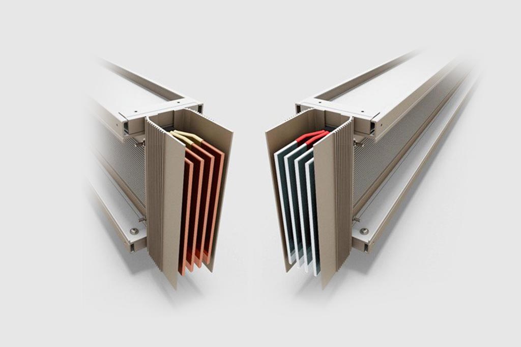
Crossmars Energy Limited provides complete project solution for replacing traditional wiring and distributing systems through Busbar Trunking System (BBT), collaborating with World Renowned Manufacturer of BBT System. Our solution included Site survey, Requirement Analysis, System Designing, Supply, Installation, Testing and Commissioning etc.
Busbar Trunking System involves distribution of electrical power using set of copper/Aluminum bus bars enclosed in suitable enclosure with high degree of protection against any ingress of foreign bodies. Crossmars Energy Limited offers both Copper and Aluminum BBT products. The following products are available to meet the specific client requirements.
Why Use Busbar Trunking?
Busbar Trunking vs Cable
| S.No | Busbar Trunking | Cables |
| I | Features : | |
| Finishing is very good, hence adds to aesthetics of building | Improper laying of the cables may spoils the aesthetics of building | |
| Multiple floor building power feeding can be done with single Bustrunking system | Multiple floor building power feeding has to be done with multiple cable sets. This make the complete system cumbersome. | |
| Power tap off can be done from the single system installed.. In case the load changes we have to just replace the Tap off boxes of higher rating. | Not possible. Additional cables to be laid till the particular floor. | |
| II | Voltage Drop : | |
| The voltage drop of bustrunking is less as compared to cables. | The voltage drop is more in cables. | |
| III | Structure : | |
| Example for 3200A(Cu) dimensions : 151(w)x340(h) and light in weight | Cables and its structure 700mm wide i.e., cable tray etc. is very heavy and occupies more space. | |
| Total run is made up of multiple elements which are joint together. Thus making the complete system maintenance friendly. | As single length of multiple cables are installed, making it maintenance non friendly. | |
| Easy retrofitting of the element is possible in case the location and consumer load | Easy retrofitting of the element is not possible in case the location and consumer load | |
| Totally enclosed, cannot be tampered. Fit and forget system2 | Insulation can wear off with time. Can get damaged by rodents. Has to maintained on regular basis. | |
| IV | Degree of Protection : | |
| IP-54 for plug in type, IP55, 65 ,66,68 for feeder | No protection as such | |
| No Special protection is to be taken for installation as busbars are now available upto IP68 protection class | Special protection is to be taken for installation in OUTDOOR area. | |
| V | Enclosure : | |
| It consists of busbars in a protective enclosure, including straight lengths, fittings, devices and accessories. | Cables are simply insulated with multiple layers of PVC. | |
| High Short circuit strength & high fire protection | Low Short circuit strength & low fire protection | |
| VI | Termination : | |
| Direct termination through busbars | The method for cable termination is very cumbersome. | |
| Termination is simple and easy. | Additional supports are required to hold the cables inside the panel. | |
| Have a highly compact structure and can be bent up to 90 degree. | Cables are generally installed in bundles & with such a cross section that they can not be bent tightly. | |
| VII | Time & Cost Consumption : | |
| When sizing busbars the designer only needs to make calculations on a single riser which reduces design time and costs. | It is necessary to protect each cable individually with a fuse and when laying the cables in bundles it is necessary to anchor them properly so that they can withstand the electrodynamic forces generated in the event of a short ckt. So, the designers have to spend more time on calculations. | |
| VIII | Use of additional items : | |
| No additional supports are required. | Heavy labor is required to lay the cables | |
| No extra holes/cutouts are required. | Holes to be made in the gland plate for fixing cable glands | |
| No cable tray is required, supported on ceiling / wall. | Cable tray or the digging of the trench is required to lay the cables | |
| No special tools are required. | Special tool are required for crimping the cable lugs | |
| Design verified switchgear assembly, limits from manufacturer’s catalogue | Limits depend on the laying method and cable accumulation. The derating factor must be determined / calculated | |
| IX | Halogen Free : | |
| Principally free from halogen. | PVC cables are not free from halogen. Halogen-free cables are very expensive. | |
| X | Damage by rodents : | |
| Busbar systems cannot be damaged by various rodents, which prevents the steel /Aluminium casing. | PVC cables are not free from halogen. Halogen-free cables are very expensive. |

